
Remember me


Assembling the circuit board is done in four steps: applying solder paste using a solder stencil, placing surface-mount components, reflow soldering with a hotplate or oven, and finally hand-soldering through-hole components.
2a. Apply solder paste
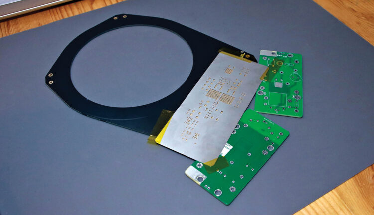
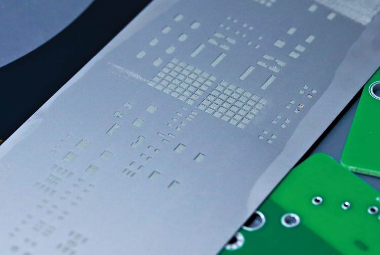
Using a solder paste stencil makes it easy to reflow-solder an entire board at once. The stencil itself is laser-cut from very thin metal.
Good results require the stencil to lie as flat as possible against the PCB. To prevent the stencil from flexing over the edges of the board, use same-thickness bare PCBs as shims. The green ones shown I had left over from prototyping, but you’ll have material available regardless because PCBs are fabricated and shipped in batches of 3 to 5 or more.
Carefully align the stencil on the PCB, then secure it with Kapton tape. Apertures in the stencil should align perfectly with the board’s plated pads.
Spread a generous glob of well-mixed solder paste at one edge of the stencil. Using a thin, stiff squeegee, swipe the solder paste across apertures in the stencil. Hold the squeegee at about a 45° angle. The goal is to swipe the solder across the surface of the stencil, not jam it downward into the holes. I use a purpose-made steel squeegee tool, but something like a putty knife or an old credit card also works great.
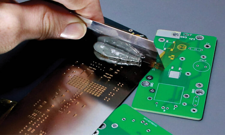
Try to complete the application in a single pass, or two at most. If you completely mess up, clean the board and try again. Scrape leftover paste back into the jar.
Carefully lift away the stencil. You should see small amounts of grey solder paste sitting cleanly and neatly atop each pad. The applied paste has a working lifespan of several hours before it dries up.
2b. Place surface mount components
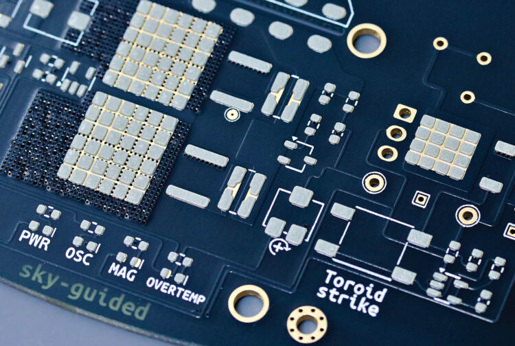
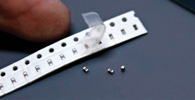
This board was designed to use 0603-size surface mount components. By modern electronics standards 0603 is medium-sized; by any normal human standard it’s miniscule. You’ll need sharp tweezers, good lighting, and either young eyes or a little magnification. Nonetheless, if you have a reasonably steady hand, then assembly is easier than you might think.
You can find the location of each component in the interactive bill of materials (IBOM) file ibom.html, located inside the /bom subfolder. Open the IBOM file in a web browser. If you bring a laptop to your work area then you can see the exact location of each component highlighted on mouseover. Otherwise, turn on the “fab” layer under the gear menu icon and make a print copy.
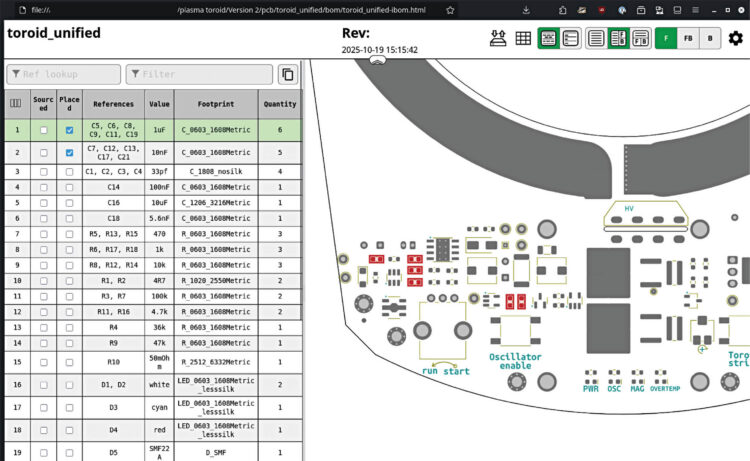
The IBOM is arranged by component type and roughly in order of smallest to largest, which is a good assembly sequence. Check off components as you place them.
Use tweezers to place each component. The parts can be dropped gently onto the solder pads and given a teeny tap to stick to the paste. You don’t need to squish or smear the solder. It’s OK if components are a bit crooked, because surface tension of the melting solder will pull everything into perfect alignment.

Using tweezers to place components.

Parts stuck to solder paste.
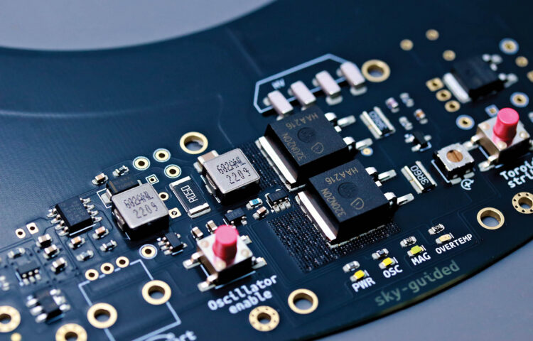
Pay careful attention to the orientation of diodes and integrated circuits. ICs will usually have a tiny dot to mark pin 1, which corresponds to an arrow on the PCB’s silkscreen paint. Diodes have a small line on the cathode. LEDs vary; some have the cathode marked in green, some only have glyphs on the underside, and some have subtle distinctions in electrode shape. Check the component datasheets if you’re unsure.

Arrow by pin 1.

LED cathodes marked in green.
Once all the surface mount components are placed, you’re ready to reflow the board.
2c. Reflow soldering
I’m using a soldering hotplate for my PCB solder reflow. A reflow oven would work great too. Some folks go as low-tech as a kitchen skillet!
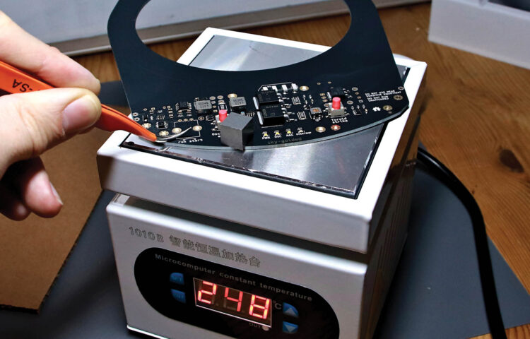
Your solder paste will recommend a reflow profile: holding and ramping between particular temperatures at particular rates. In practice the exact parameters are pretty forgiving. I’ve had great results from programming the hotplate to the max temperature recommended by the solder manufacturer, then placing the board on the cold hotplate and letting the plate warm up to full temperature at its own pace.
As the board heats up, the solder paste will start to sizzle and smoke. Don’t breathe this. Near the peak temperature, the solder joints will melt and turn to shiny liquid. The solder on the bigger components, and near the periphery of the board, will probably be the last to melt.
Once you’re sure everything has melted, use your tweezers to lift the board straight off the hotplate — don’t immediately tilt it or components will slide off. Set the board aside to cool.
2d. Inspect
Before moving on, examine the board thoroughly. Watch out for solder bridges and pins that didn’t fully reflow. Pluck away any balls of excess solder.
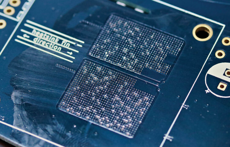 Leaked solder.
A tiny amount of solder and flux residue may have leaked through to the underside of the board below the MOSFETs, through the thermal conduction grid of tiny plated holes. You’ll especially need to remove any excess solder in this area or it could cause destructive shorts to the heatsink. Wipe away flux residue with isopropyl alcohol (aka isopropanol).
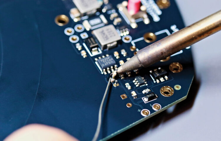
2e. Hand-solder through-hole parts
Hand-solder the remaining through-hole components. Start with the underside components, again working smallest to largest. Do the top-side potentiometer last, then trim its legs flush with the board’s underside.
Comments (0)